Products

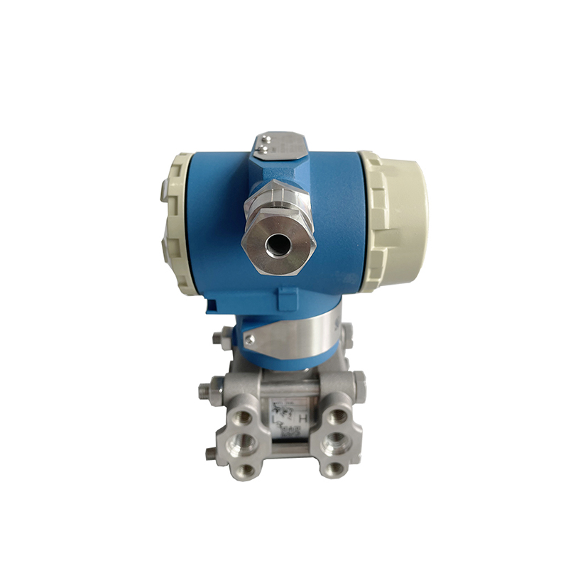
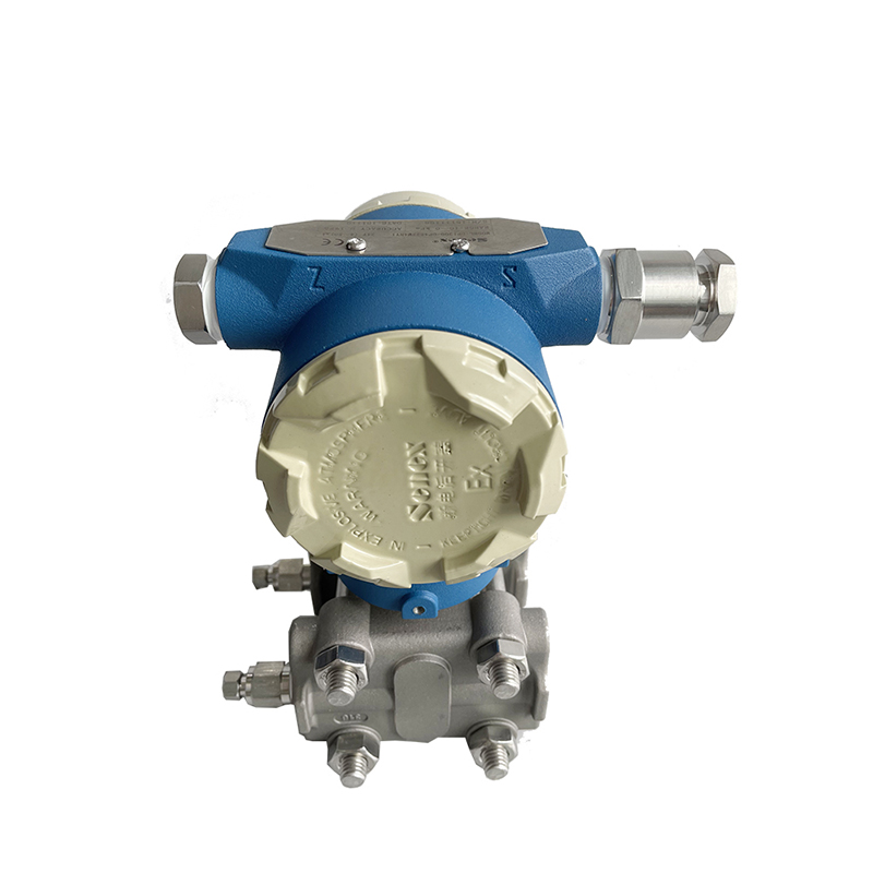
DP1300-DP Series Differential Pressure Transmitter
DP1300-DP Series differential pressure transmitter has high measurement accuracy, strong overload capacity, good stability, easy installation, and is suitable for various types of pressure measurement applications. It is widely used in power, metallurgy, petrochemical and pharmaceutical industries.
1. The monosilicon type belongs to the latest generation of differential pressure sensor technology, and has excellent performance in measurement accuracy, turndown ratio, overvoltage capability, and stability.
2. Compared with differential pressure sensors of the same accuracy level, the yield rate of monosilicon type is much higher than that of other early technologies such as capacitive type. There is no need for precision screening in the production process, and mass production of high-precision products can be realized.
| Standard Specification | Span adjustment based on standard zero point, with stainless steel 316 L diaphragm, filling liquid is silicone oil. | ||||||||||||
| Performance Specification | Reference Accuracy of Adjustment Span | (Includes linearity from zero, hysteresis and repeatability): ± 0 . 075% | |||||||||||
| TD> 10 ( TD=Maximum span/adjustment span): ±(0.0075×TD)% | |||||||||||||
| Square root output accuracy is 1.5 times the linear reference accuracy above | |||||||||||||
| Ambient Temperature Effect | Span Code | - 20℃~65℃ Total impact | |||||||||||
| A | ±( 0 . 45×TD+ 0 . 25 )% ×Span | ||||||||||||
| B | ±( 0 . 30×TD+ 0 . 20 )% ×Span | ||||||||||||
| C/ D/ F | ±( 0 . 20×TD+ 0 . 10 )% ×Span | ||||||||||||
| Span Code | - 40℃~- 20℃ and 65℃~85℃ Total impact | ||||||||||||
| A | ±( 0 . 45×TD+ 0 . 25 )% ×Span | ||||||||||||
| B | ±( 0 . 30×TD+ 0 . 20 )% ×Span | ||||||||||||
| C/ D/ F | ±( 0 . 20×TD+ 0 . 10 )% ×Span | ||||||||||||
| Over-span Effect | ±0 . 075% ×Span | ||||||||||||
| Span Code | Amount of Influence | ||||||||||||
| Static Pressure Effect | A | ±( 0 . 5% Span)/ 580Psi | |||||||||||
| B | ±( 0 . 3% Span)/ 1450 Psi | ||||||||||||
| C/ D/ F | ±( 0 . 1% Span)/ 1450 Psi | ||||||||||||
| Performance Specification | Overvoltage Effects | Span Code | Amount of Influence | ||||||||||
| A | ±0 . 5% ×Span/580Psi | ||||||||||||
| B | ±0 . 2% ×Span/ 2320Psi | ||||||||||||
| C/ D/ F | ±0 . 1% ×Span/ 2320Psi | ||||||||||||
| Long Term Stability | Span Code | Amount of influence | |||||||||||
| A | ±0 . 5% ×Span/ 1Year | ||||||||||||
| B | ±0 . 2% ×Span/ 1Year | ||||||||||||
| C/ D/ F | ±0 . 1% ×Span/ 1Year | ||||||||||||
| Power Impact | C/D/F | ±0 . 001% / 10 V( 12~42 V DC) | |||||||||||
| Measuring Range | kpa/ mbar | kpa/ mbar | |||||||||||
| A | 0 . 1~1 / 1~10 | - 1~1 /- 10~10 | |||||||||||
| B | 0 . 2~6 / 2~60 | - 6~6 /- 60~60 | |||||||||||
| C | 0 . 4~40 / 4~400 | - 40~40 /- 400~400 | |||||||||||
| D | 2 . 5~250 / 25~2500 | - 250~250 /- 2500~2500 | |||||||||||
| F | 30~3000 / 0 . 3~30 bar | - 500~3000 /- 5~30 bar | |||||||||||
| Span Limit | Within the upper and lower limits of the span, it can be adjusted arbitrarily; It is recommended to select a range code with the lowest possible turndown ratio to optimize performance characteristics. |
||||||||||||
| Zero Point Setting | Zero point and span can be adjusted to any value within the measurement range in the table (as long as: calibration span ≥ minimum span). | ||||||||||||
| Installation Location Influence | The change of the installation position parallel to the diaphragm surface will not cause zero drift effect. If the change of the installation position and the diaphragm surface exceeds 90°, the zero position effect in the span of < 0.06 Psi will occur, which can be corrected by adjusting the zero adjustment, with no range effect. | ||||||||||||
| Output | Two-wire, 4~20 m ADC, HART output digital communication can be selected, linear or square root output can also be selected. Output signal limit: Imin= 3.9 m A, Imax= 20.5 m A |
||||||||||||
| Alarm Current | Low report mode (Mini): 3.7 m A High report mode (Max): 21 m A Non-reporting mode (hold): keep the effective current value before the fault and report Standard setting of alarm current: high mode |
||||||||||||
| Response Time | The damping constant of the amplifier part is 0.1 s; the sensor time constant is 0.1 to 1.6 s, depending on the range and range ratio. Additional adjustable time constants are: 0.1 to 60 s. The effect on non-linear output, such as the square root function, depends on the function and can be calculated accordingly. | ||||||||||||
| Preheat Time | < 15 s | ||||||||||||
| Ambient Temperature | - 40~85℃ With LCD display and fluororubber sealing ring: - 20~65℃ |
||||||||||||
| Storage Temperature | - 50~85℃ With LCD display:- 40~85℃ |
||||||||||||
| Work Pressure | Rated working pressure is divided into: 2320 Psi, 3630Psi, 5800 Psi | ||||||||||||
| Static Pressure Limit | From the absolute pressure of 0.5Psi to the rated pressure, the protective pressure can be greater than 1.5 times of the rated pressure, and it is applied to both sides of the transmitter at the same time. | ||||||||||||
| One-way Overload Limit | One-way overload up to rated pressure | ||||||||||||
| Material | Measuring Capsule: Stainless Steel 316 L Diaphragm: Stainless Steel 316 L, C-276 alloy Process Flange: Stainless Steel 304 Nuts and Bolts: Stainless Steel (A 4 ) Filling Fluid: Silicone Oil |
||||||||||||
| Protection Class | IP67 | ||||||||||||